How To Evaluate LatStab Index:
The Dynamic Stability Index (DSI) uses a
unified rating scale to predict how a hull will behave under
real-world operating conditions.
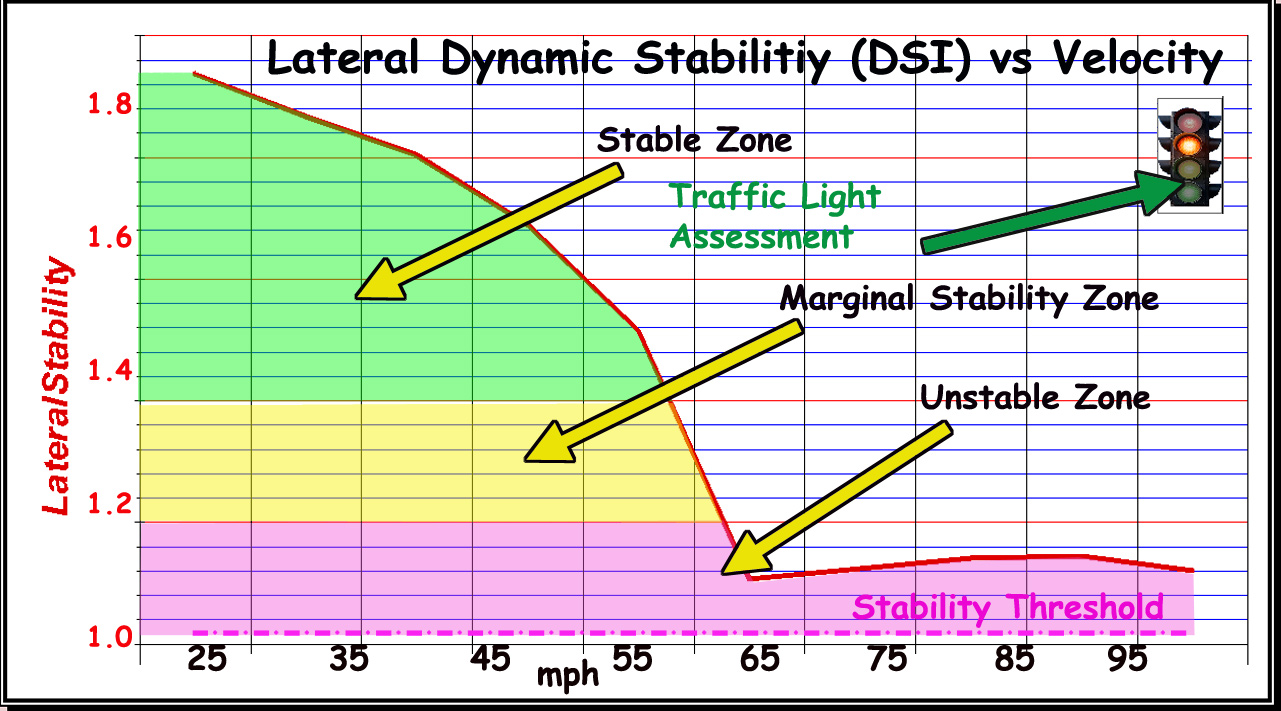
Greater value is better. DSI > 1 is more stable, DSI < 1 less stable. [see
Graph #69, DSI>1 is better].
-
GOOD: DSI > 1.2 → Good dynamic
stability; hull exhibits well-damped roll response.
-
MARGINAL: 1 ≤ DSI ≤
1.2 → Marginal stability; hull may feel sensitive but remains
controllable.
-
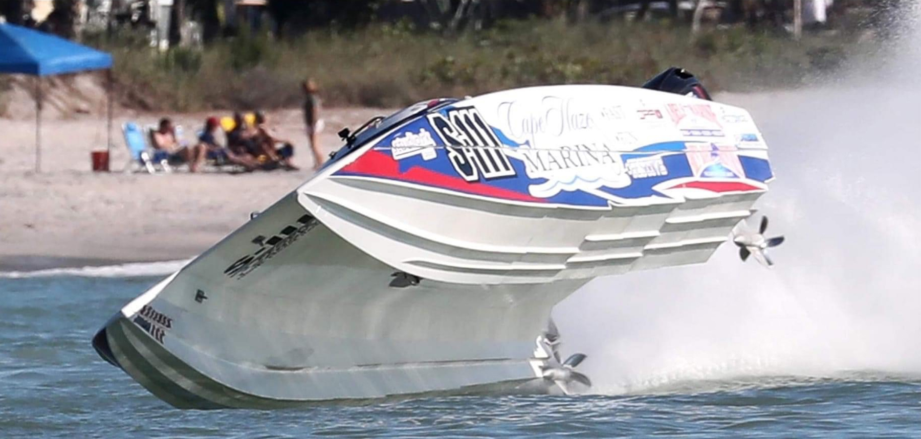
UNSTABLE: DSI < 1 → Poor dynamic stability; risk of
oscillatory or divergent roll behavior; onset of chine-walk,
track rolling, hook.
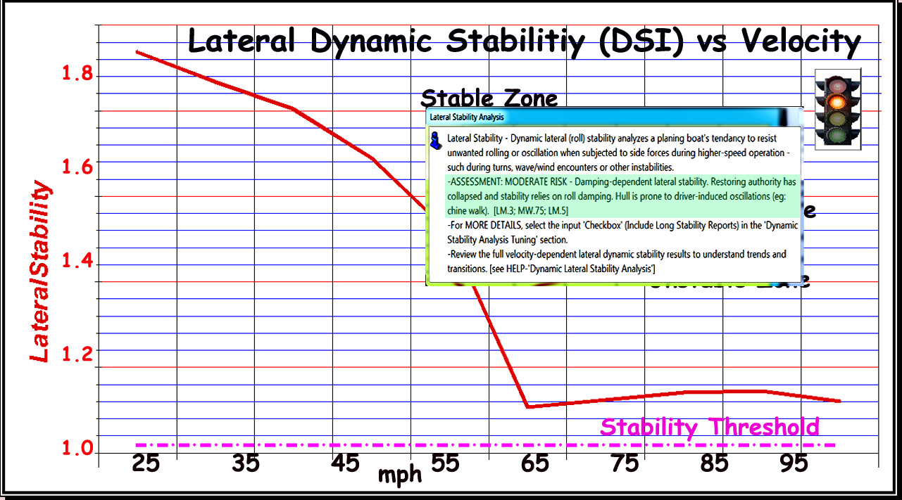
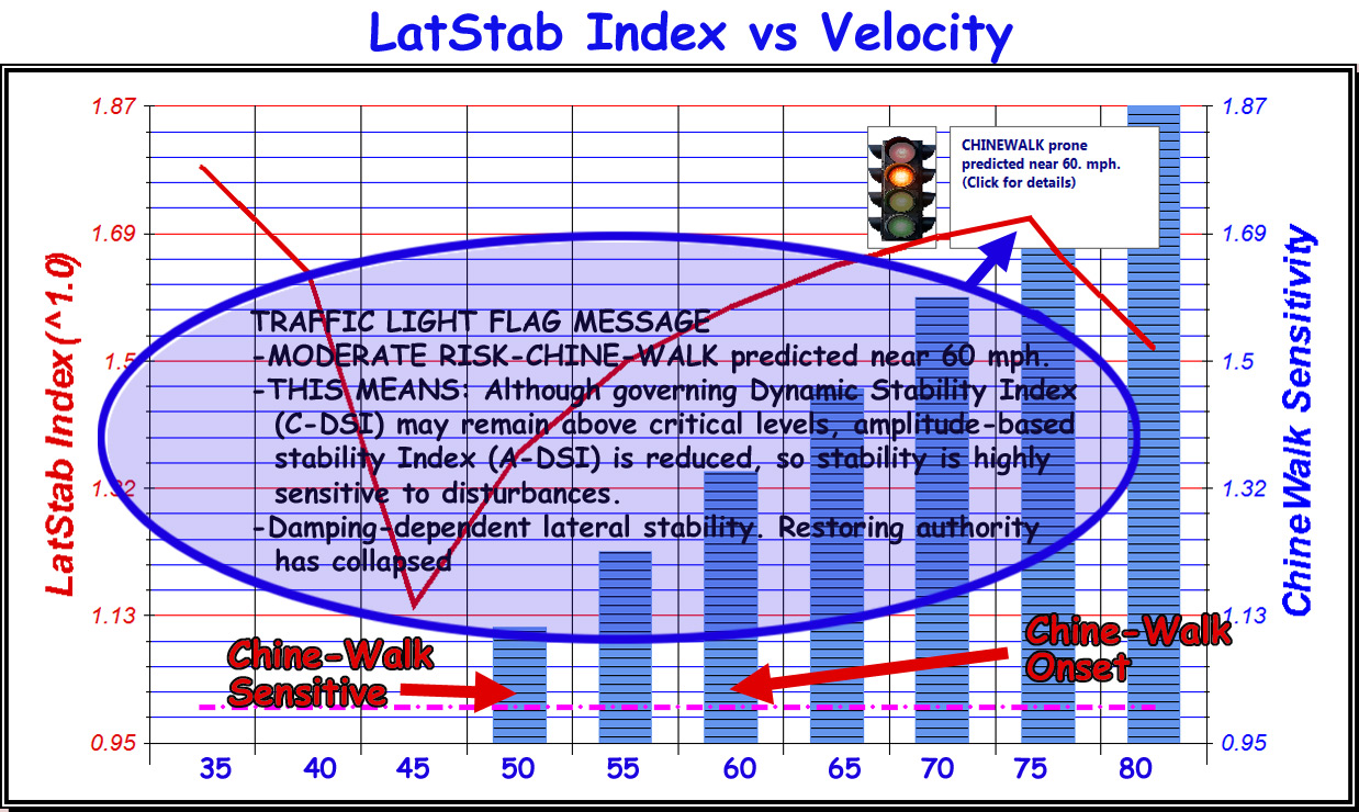
NOTE: Stability indicator results are not
ONLY value-based, see the 'trend-based' ASSESSMENT provided in
'Performance Summary Report' and the 'TRAFFIC LIGHT' symbol on
this graph. CLICK on 'TRAFFIC LIGHT' symbol for DETAILED
STABILITY REPORT.
Read on for explanation
of these analytical indicators...
Advanced Methodology
The presented (AR®)
analysis technique introduces a dynamic, energy-based method for
evaluating lateral stability across the full operating speed
range. Developed through extensive hydrodynamic research,
modeling and full-scale testing, it captures the complex
interactions of roll forces, damping, geometry, and pressure
fields within a single, unified framework.
By separating Restoring
Authority from Damping Effectiveness and identifying which
physical mechanism governs stability at each speed, the method
accurately predicts instability onset before it manifests on the
water. Implemented within TBDP/VBDP software, the approach
provides designers with a practical, physics-based tool to
assess real-world handling behavior and apply targeted design
corrections early in the design process.
TBDP©/VBDP© Lateral
Stability Analysis even accounts for dynamically changing
damping effects of vee-pads, center-pods, multiple Lifting
Strakes, etc.
"This new dynamic lateral stability analysis by
AeroMarine Research delivers a major
step forward in predicting a boat’s true stability behavior
across all speeds, from the first moments of planing to the
highest performance speed ranges. Despite the depth and sophistication of the
method, the resulting 'Dynamic Stability Index' makes it
amazingly easy for users to assess stability quickly and
confidently." [PBDesign magazine, Dec 2025]
Making it Easy:
TBDP©/VBDP© presents a
reporting format that makes the results and recommendations easy
to understand...
TBDP©/VBDP© presents a full
range of reporting information that makes the results and
recommendations easy to understand.
For each of the Stability
measures, the software does ALL the work behind the scenes, and
gives both DETAILS and also gives the 'GOOD/NO GOOD' summary of
all considerations. [Check out
'Easy Results View' here]
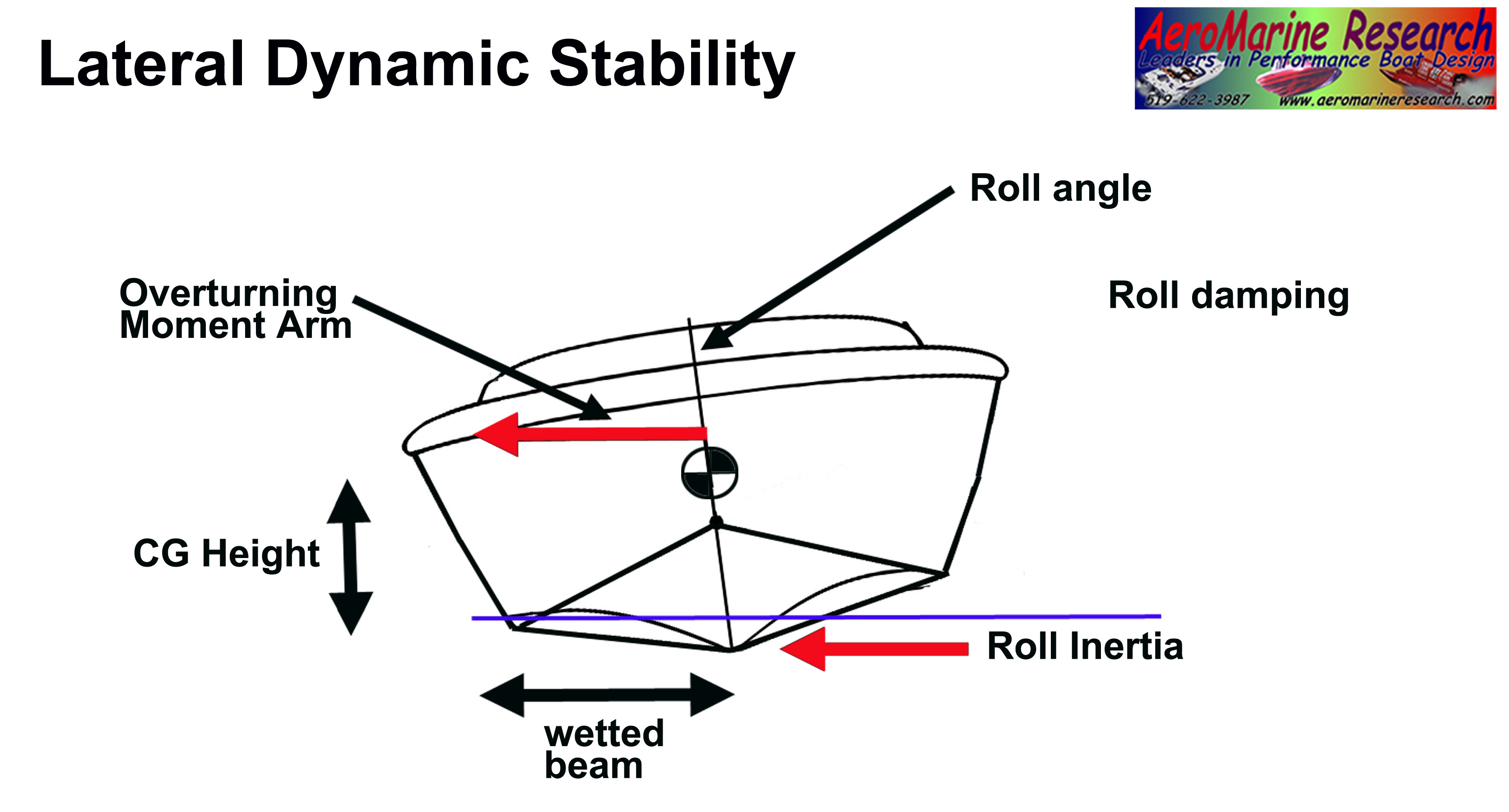
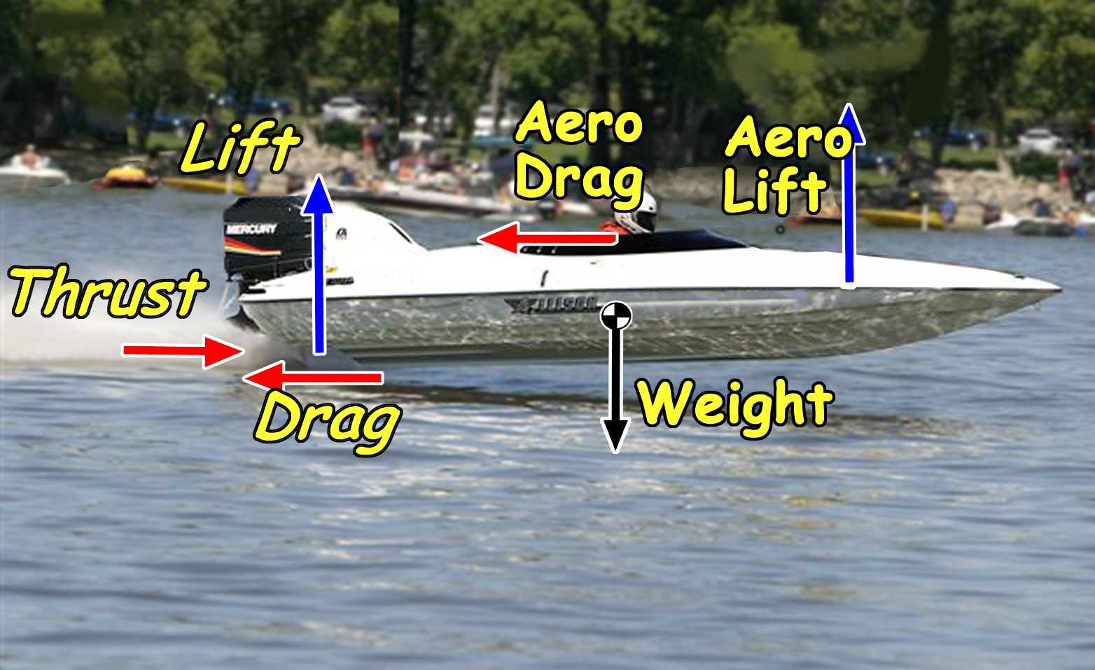
What Is Lateral Dynamic Stability?
Lateral dynamic stability describes a hull’s ability to resist
growing roll motion when subjected to small disturbances such as
waves, steering inputs, or asymmetric lift. A hull is laterally
stable if these disturbances decay with time, and unstable if
they grow from cycle to cycle. Therefore, lateral stability
cannot be determined solely by static equilibrium.
Consequently, lateral
dynamic stability cannot be fully characterized by static
equilibrium methods alone. While a hull may possess positive
geometric restoring stiffness at rest, it can exhibit dynamic
instability at high velocities if hydrodynamic roll energy
amplification exceeds the system's damping capacity. This
physical threshold marks the onset of non-linear roll
oscillations, commonly known as 'chine walking'.
Dynamic lateral stability
is governed by three interacting factors: ·
-
how much roll energy is
generated by disturbances,
-
how effectively that
energy is dissipated each cycle,
-
how strongly the hull
restores itself as heel develops.
Understanding stability
therefore requires evaluating motion over time, as well as
forces at equilibrium.
Why Traditional
Methods Fall Short
-
Savitsky-Based Analysis
- Savitsky theory evaluates planing hull behavior using
static equilibrium of forces and moments. Lateral stability
is inferred from restoring stiffness and lift distribution
at individual operating points, implicitly assuming that
roll disturbances decay naturally. Roll inertia, energy
persistence, and speed-dependent amplification mechanisms
are not modeled. As a result, Savitsky-based methods cannot
predict when or why lateral instability will develop as
speed increases.
-
CFD Software Analysis
- CFD software tools provide detailed pressure and force
distributions at specific speeds, but these results are
typically isolated snapshots . They do not dynamically evaluate whether
roll motion grows or decays over successive cycles, nor do
they efficiently capture regime transitions across a speed
range. Even 'high-end' add-ons for CFD software are
computationally expensive and often fail to translate
directly into real-world handling predictions.
A Dynamic
Energy-Based Stability Framework
This presented (AR®) method
treats lateral stability as a dynamic energy balance problem.
Instead of simply testing whether restoring forces exist, it
evaluates whether roll energy introduced by disturbances is
removed faster than it accumulates. Two complementary stability
mechanisms are both necessarily evaluated: ·
-
A-DSI (Amplitude-Limited
Stability Index) - measures the hull’s inherent
restoring authority and ability to resist and limit roll
motion as heel amplitude increases. This is an
advanced modeling indicator (developed by AR®) that more
accurately represents higher velocity stability behaviors.
This indicator represents a hull's dynamic 'Restoring
Authority' - the hull’s ability to generate corrective roll
moments as heel amplitude develops - or 'how strongly the
hull shape itself pushes back against rolling as it leans'.
It reflects hull geometry, lift distribution, and effective
roll leverage.
-
C-DSI (Cycle-Limited
Stability Index). - based on the classical
damping-based stability formulation traditionally used for
planing hull stability assessment and is most representative
when damping mechanisms dominate the stability response.
This indicator measures how effectively the hull dissipates
roll energy over time instead of allowing oscillations to
build It captures the
combined influence of roll inertia, hydrodynamic damping,
and flow interaction.
Both mechanisms are
evaluated continuously across the operating speed range.
Dynamic Regime
Identification (Λ)
The Dynamic Regime
Indicator, Lambda (Λ), identifies which physical mechanism
governs stability at each operating condition by comparing
available restoring leverage to overturning leverage. Lambda
determines whether stability is governed primarily by restoring
authority (A-DSI) or damping effectiveness (C-DSI).
The AR® analysis
technique evaluates all of the conditions:
-
Λ > 1 —
Restoring Authority-Dominated
Regime (A-DSI) - Restoring authority controls
stability. Geometry and lateral lift engagement are the
primary stabilizing mechanisms.
-
Λ < 1 — Damping-Dominated Regime
(C-DSI) - Stability depends primarily on energy
dissipation. Roll inertia and lift concentration dominate,
and instability onset becomes more likely.
-
Transitional Regime (A-DSI
and C-DSI) Both mechanisms contribute. Stability
is highly sensitive to speed, trim, and loading, and small
design changes can have large effects.
This regime awareness is
extremely helpful to the designer because it explains not just
whether a hull is unstable, but why.


