|
Advanced aerodynamic
analysis technique gives highly accurate lift and drag contributions
to tunnel boat performance predictions & optimization.
Aerodynamic research
has been advanced by AeroMarine Research®, extending traditional
aerodynamic algorithms to account for the complexities of 'ground
proximity', 'end-limited pressure' conditions (tunnel sides), non-symetrical
upper/lower aerofoil surfaces. AR® has developed unique algorithms
to establish highly accurate aerodynamc lift, drag and dynamic stability
results that are specific to tunnel hull, power catamaran, vee hull
and vee-pad hulls. TBDP is the only software that includes
Aerodynamic 'Ground Effects'
analysis.
AR conducted unique aerodynamic research that included
wind tunnel assessments, ground effect experiments, and
complex hydrodynamic research, all of which greatly advanced the
understanding of the intricacies of tunnel hull behavior.
Ground-effect tests were conducted in a high-speed, sub-sonic,
wind tunnel using an image-wing (reflection) method. [The
image-wing technique uses an identical model mounted inverted
with respect to the test model in flow stream, and correlates
well with results of a body moving over a surface.]
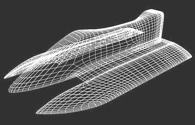
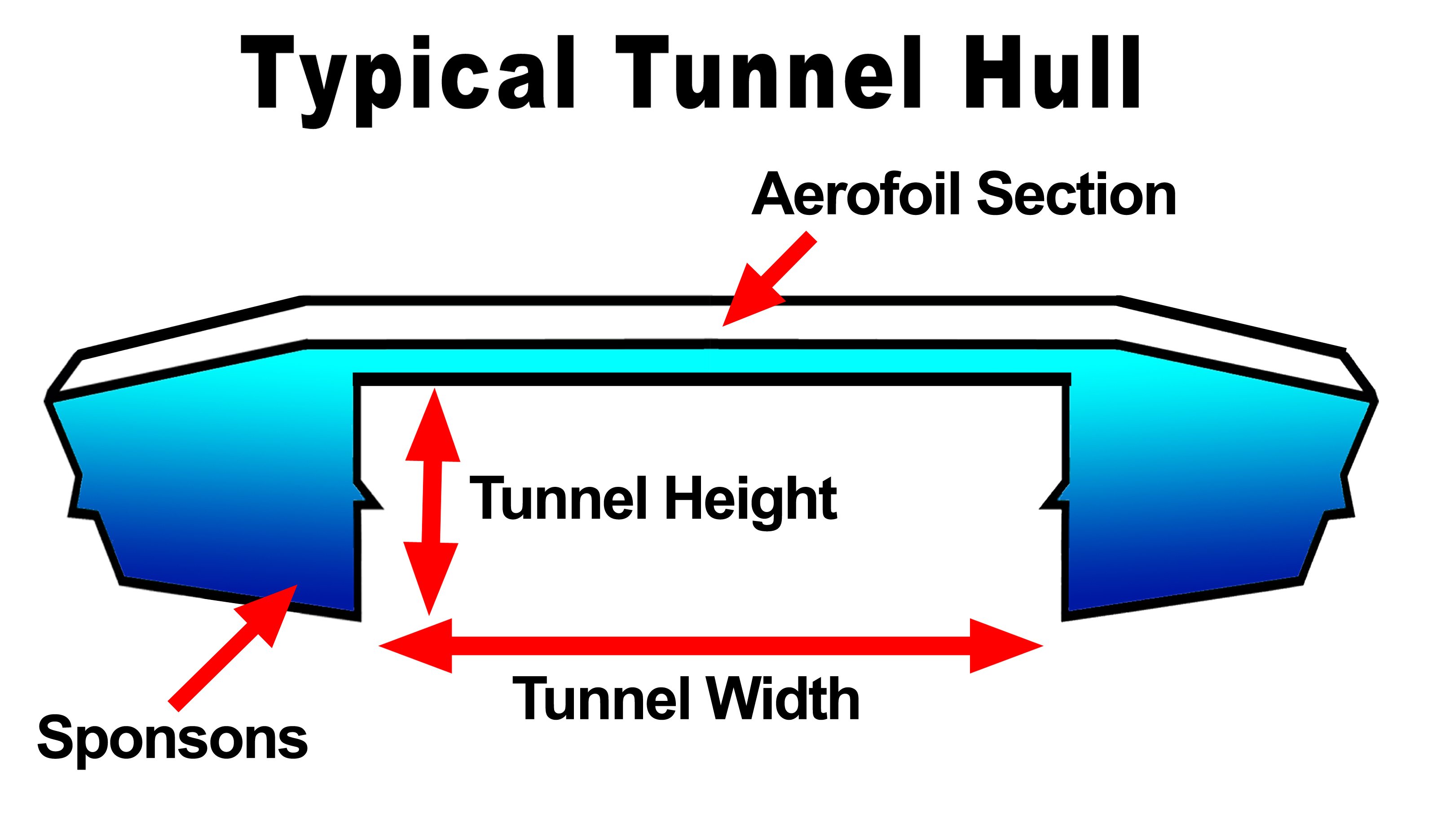
Tunnel boats demonstrate exceptional
performance because they have a 'wing' or aerofoil built-in
to their design. The tunnel “roof” and the upper
deck surface form the lower and upper surfaces of the aerofoil,
respectively. When properly designed, it is this aerofoil,
and the aerodynamic lift it generates using
aerodynamic 'Ground Effects', that gives the tunnel boat
its great performance. A performance tunnel boat must count on the
sponsons for some of the lift for the hull, just as a deep-vee boat
must depend on its narrow running surface to support its weight.
The tunnel hull (and many vee hulls) has the additional advantage
of being able to further reduce the water drag by supplying lift
from its aerodynamic surfaces.
'Ground Effect'
- A properly designed tunnel hull can be considered as a wing in
'ground effect',
(even though it's water that it is 'flying' over). Several
design characteristics affect the influence of aerodynamic
'ground effect' on tunnel hull performance behavior, such as
wing height, aspect ratio, aerofoil thickness, end containment ('winglets'),
aerofoil shape, trim angle (AofA), etc.
For example, 'Wing Height', or 'height of tunnel roof aerofoil
above the water surface'. In most cases, as the tunnel roof runs
closer to the water surface the lift generated increases. This
is called 'ground effect'. An aerofoil or 'wing' in ground
effect has very special characteristics, and the phenomenon is a
study all in itself. [See more on the 'Wings in Ground Effect',
in "Secrets
of Tunnel Boat Design" book]
We have established that a tunnel boat's aerofoil operating close to the
'ground' or water surface causes a tremendously enhanced
Lift/Drag relationship. The much higher pressures generated in
close proximity to the water surface cause an even larger
difference in pressures between the top surface and bottom
surface of the wing, resulting in higher lift forces, and
actually lower aerodynamic drags.
Key is the integration of aerodynamic forces with the other
hydrodynamic lift and drag forces operating simultaneously under
all conditions.
TBDP©/VBDP© is the only powerboat design software that
accounts for the complex influences of 'ground effect' on tunnel
hull performance.
Aerodynamic Lift - A properly
designed tunnel hull can be considered as a wing in 'ground effect',
(even though it's water that it is 'flying' over). Every pound
of lift that can be generated by this 'wing', is one less pound
of lift that doesn't have to be supplied by the hydrodynamic lifting
surfaces ‑ which bring unwanted water drag.
Many inter-dependance factors are involved
in creating the lift generated by the tunnel and the deck surfaces,
or this 'wing'. This consideration is the same for all sizes,
configurations, weights, speeds, power of tunnel boats and catamarans.
The main contributors can be summarized as:
a) Airspeed
b)
Angle-of-attack
c) Effective aerodynamic Lifting Area
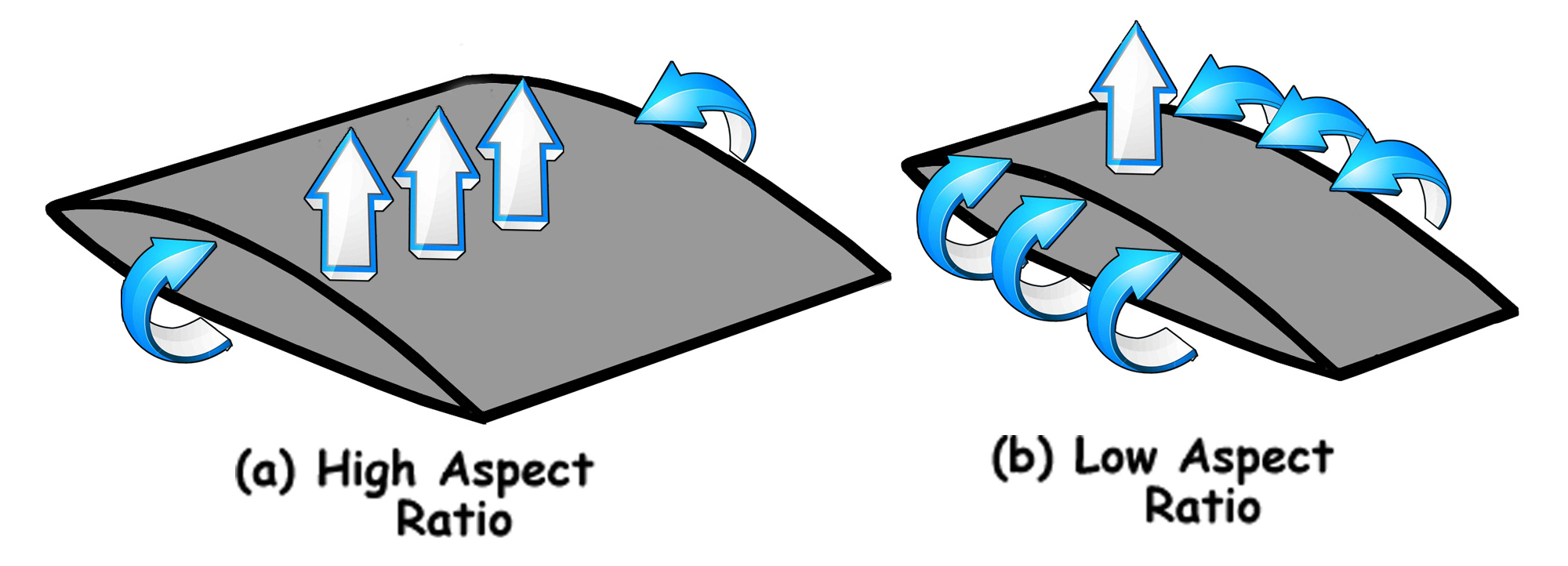
d)
Aspect Ratio of Tunnel (chord/width)
e) Height above the water
surface
f) Aerofoil shape of tunnel cross-section
g) Aerofoil
thickness
h) Surface condition (roughness) of exposed areas
[TBDP©/VBDP© performs
for all hull types, all sizes, all powers, all speeds.]
Complex fluid flow modeling specifically
for tunnel and vee hulls allows accurate computer modeling of these
complex designs that fly in air and on water. Aerodynamic
'Ground Effects' are analyzed and included in performance
analysis of tunnel hull and vee hull configurations.
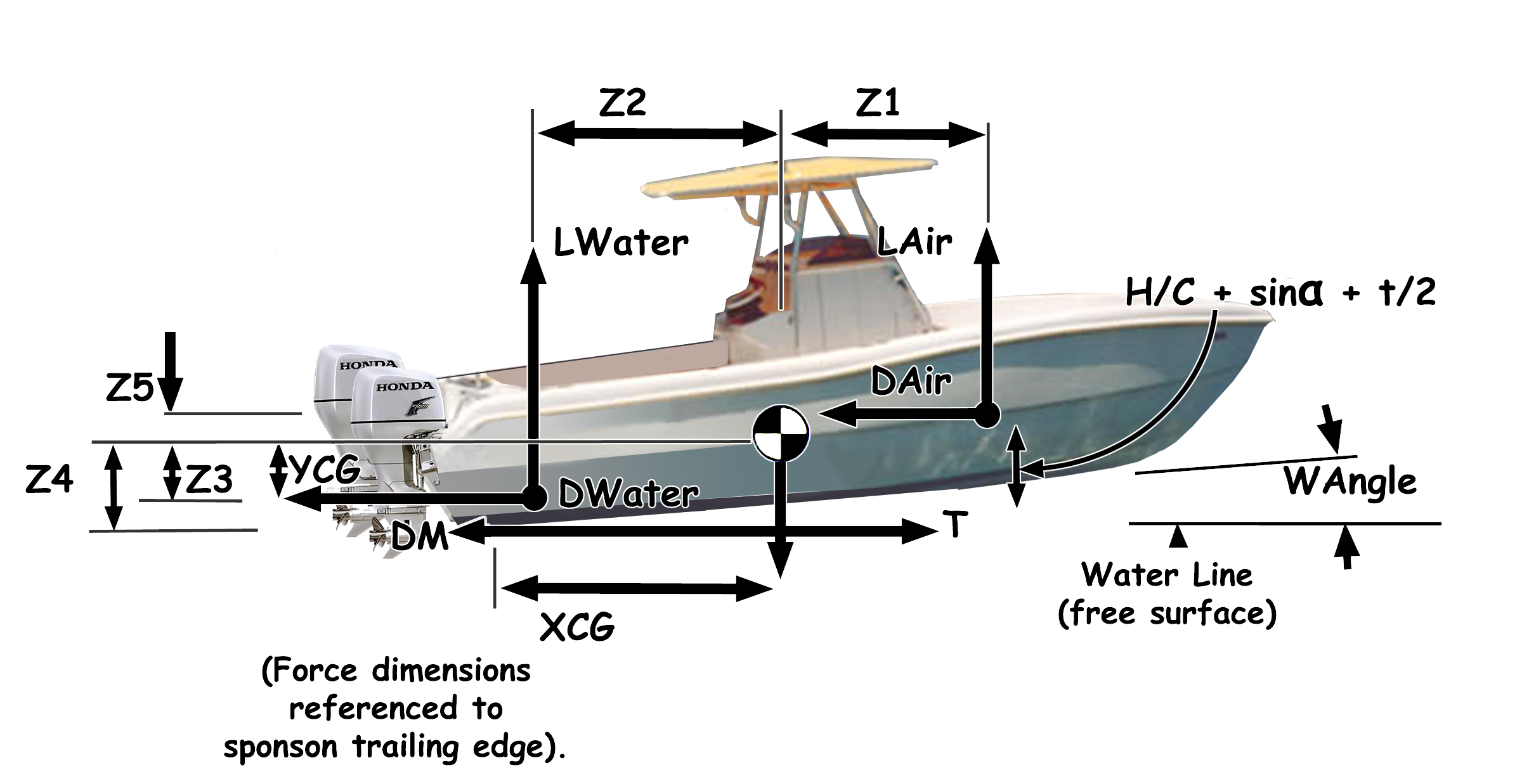
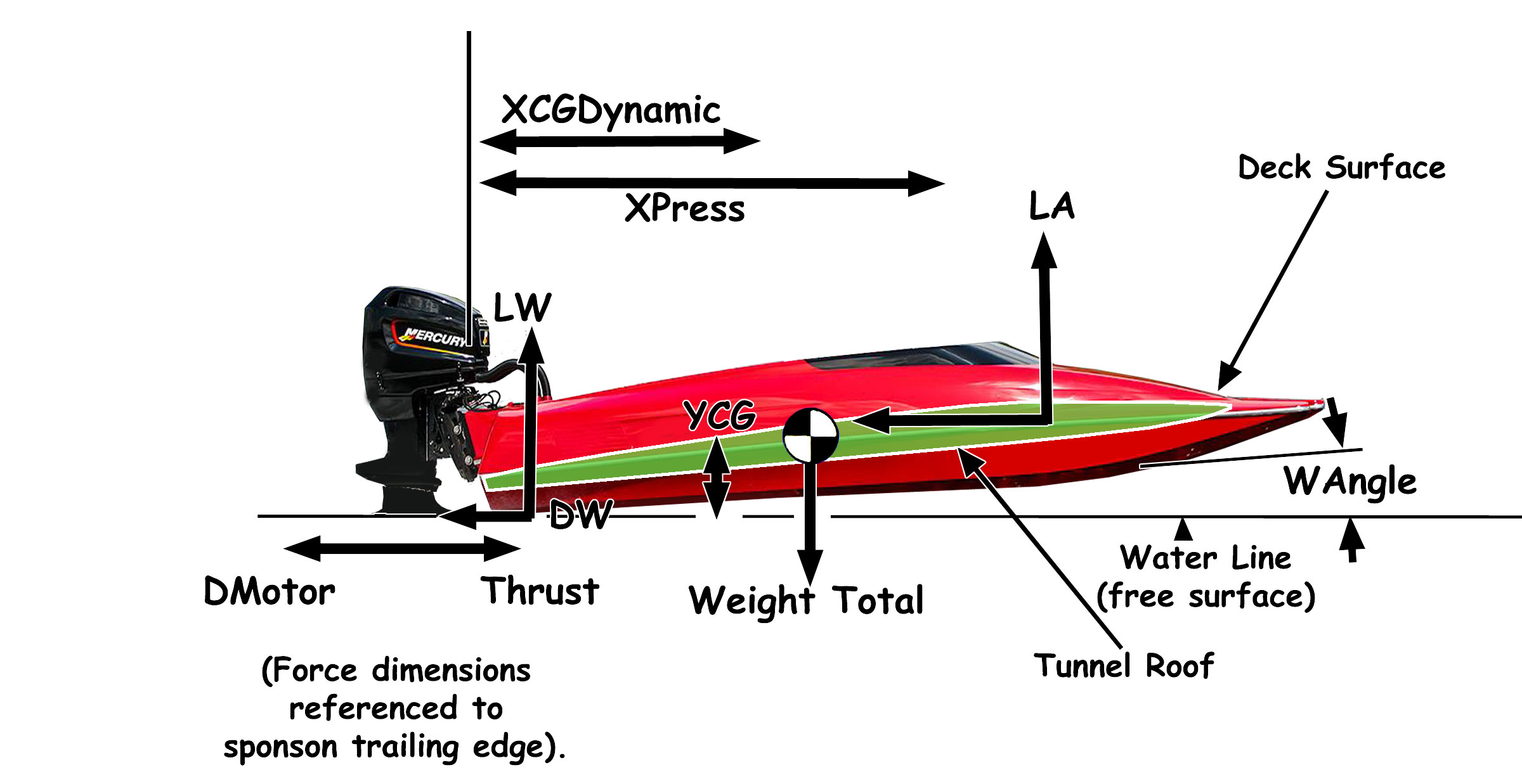
Important Considerations -
Forces acting on a tunnel hull must include
the influence complex planing surfaces (steps, lifting strakes,
centre-pad/pod surfaces, etc.), and of non-planing forces (aerodynamic
contributions from low aspect ratio ground effect hull forms, etc.).
While the normalized derivation for lift from hydrodynamic surfaces
is...
LA
= ½ • ρA
• V2
• SA •
CLA
where:
LA
= hydrodynamic (water) lift
ρA
= density of water
V = velocity
SA
= effective wetted surface area
CLA=
lift coefficient
An advantage of tunnel hull designs is the entrapment feature
of the lower aerofoil surface or 'tunnel' section, through the 'end-plate'
provided by outboard sponsons. Normally higher aspect ratio
wings tend to increase net lift because mainly, of the reduced opportunity
for the 'escape' of high pressure air around the 'wing tips' to
the upper surface. This 'escape' of air causes what is called
a 'wing-tip vortex', reducing lift and increasing drag. The
outboard sponsons on each side of the tunnel section, act as 'wing
end plates' that restrict this 'escape' of airflow, enhancing aerodynamic
performance.
The establishment of effective surfaces and related CLA
is necessarily complex. The above influencing variables are changing
constantly with hull velocity, making the accurate accomodation
very complex. What's more, each of these variables are interdependant
(on each other), so the accurate analysis of CLA, total Lift
and total Drag is tricky.
Aerodynamic Drag
-
The total drag created by the hull must be overcome by the available
thrust - namely the engine/propeller. The drag of a tunnel
hull is made up of both aerodynamic or 'air' drag (drag from the
tunnel/deck surfaces, appendage air drags such as driver, cockpit
area, motor, etc.) and hydrodynamic or 'water drag' (from the planing
sponsons and motor appendages under water).
As with tunnel lift, the air drag increases primarily with the
square of the velocity and as angle-of-attack increases.
This air drag originates in three (3) forms:
a) Skin Friction
b) Induced Drag
c) Profile Drag
Also, the aerodynamic lift/drag is strongly influenced by the
complex interdependence of hydrodynamic Lift/Drag and other appendage
drags (cockpit
aero drag,
cavity drag, engine
lower unit
drag, etc.) - all affecting CLA, SA
and LA of aerodynamic
lifting surfaces.
'Aerodynamic Roughness'
also affects aerodynamic Lift/Drag coefficients based on
relative aerodynamic smoothness of deck, tunnel, cockpit
surfaces, and should be accomodated.
[The analysis methods in 'Secrets
of Tunnel Boat Design - Second Edition' [ISBN#
978-0-9780586-1-6, pub: 2024] and AeroMarine
Research TBDP©/VBDP©
software demonstrate the development of proven algorithms that solve
all of these challenges accurately.]
Aerodynamic Center of Pressure - The
Lift forces generated by a tunnel hull 'wing' act through it's
'Center of Pressure', (CofP). This CofP location affects
the total balance of forces of the boat, and hence,
dynamic stablity. The aerofoil shape affects the
location of the CofP. The CofP location also changes with
Veloctiy and 'Trim Angle'. As this CofP location changes
during acceleration or deceleration, so does the dynamic
stability, so aerofoil selection is important to optimize the
balance of more/less lift with change in stability.
Sponson Sides Enhance Aero
Lift - A wing derives its lift by the
difference between a high pressure on the underside of the wing
compared to a lower pressure on the topside. This difference in
pressure results in an upward force. Some airplanes attain
improved lift by adding ‘wing-tip-ends’ or ‘winglets’ that
prevent airflow from escaping around the end of the wing,
causing ‘wing tip vortices’ and reduced lift/drag efficiency.
An advantage of tunnel hull designs is the entrapment feature
of the lower aerofoil surface or 'tunnel' section, through the
‘built-in’ wing-tip ends formed by the sponsons on either side
of the tunnel section. This significantly increases the
efficiency of tunnel lift with more lift and less drag
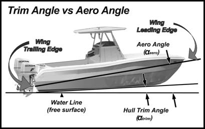
Trim Angle vs Aero Angle
-
Some tunnel boats are designed so that the 'wing' portion of the
hull will operate at an incrementally higher angle of attack
(aero angle, αaero) compared to the hull 'trim angle' (αtrim).
This feature is quite common in many tunnel hulls and power
catamaran designs, particularly weight and power sensitive
setups. The αaero feature is easily identifiable by observing
the tunnel height at the bow of the boat at a higher dimension
than the height of tunnel at the transom. The higher angle of
the 'wing' hull section allows for better seaworthy behavior in
heavier waves and also achieves more aerodynamic lift. So, when
the hull trim angle (αtrim) is say, 3°, the 'wing' experiences a
local angle of attack (αaero) of 5°. This feature generates
higher aerodynamic Lift (and also higher Drag), and is often
more beneficial to overall performance.
Dynamic Stability -
When one of the many influencing forces change, the
aerodynamic lift/drags and WAngle (trim angle) and
dynamic stability are systematically affected. The analysis
to balance these inter-dependent forces throughout velocity range
is complex, and is key to accurate performance prediction.
The AeroMarine Research TBDP©/VBDP©
software doesn't use any 'C' constants, 'shape coefficients' or
'speed factors' to simulate different hull types, shapes or velocity/size
ranges. - it analyzes all design and dimensional aspects of each
hull from first engineering principles, proven by research and full-scale
testing. [This is a unique feature of TBDP©/VBDP©, as most
all other performance analysis software products rely on choosing
'fudge-factors' to adjust results to expected hull types! TBDP©/VBDP©
software gets the right answer based on pure hull design. No
fudge factors are required. ]
TBDP©/VBDP© software uses Finite
Element analysis techniques to accurately calculate the many affecting
hydrodynamic factors that are constantly changing and highly influence
each other. The power of these techniques and the software allows
for comprehensive analysis, employing engineering techniques that
include the critical inter-dependence of aerodynamic, hydrodynamic
and stability calculation methods that are key to proper Tunnel
hull design and accurate performance prediction.
Russell's development of Advanced
aerodynamic techniques were proven
through
wind tunnel testing, water channel testing and full scale
hull verification testing.
How it Works - Any performance hull will perform better when taking best
advantage of 'aerodynamic' lift. Any amount of 'aero lift' will
improve a boats performance − even a seemingly small amount.
If we compare 2 boats each weighing 1500 pounds, that means
1500 pounds of total lift must be generated by the hull. At
say, 50 mph, the first boat with no aerodynamic lift capability
requires all of its lift to be supplied from an area of wetted
planing surface. If the second boat can contribute (even only)
100 pounds of aerodynamic lift (that's only 6% of the total lift
required) then only 1400 pounds of water-lift remain to be
generated, which requires less wetted surface area and a
corresponding reduction in hydrodynamic (water) drag.
Less drag means more efficiency and better performance. In
this case, the reduced wetted surface of the second boat results
in a 9% reduction in water drag − just like gaining 10 to 15 hp
and much improved fuel economy, or an additional 5 mph!
The performance
effects of all design and setup features that influence
aerodynamic lifts, drags and dynamic stabiltiy for all Vee hull, Vee-pad hull,
tunnel hull and modified-tunnel hull types of powerboat applications
is developed by Russell. The results are highly accurate representations
of aerodynamic forces and inter-dependence with hydrodynamic
forces associated with all powerboat configurations,
using Russell's analysis techniques in the "Tunnel Boat Design
Program" and "Vee Boat Design Program" software.
Russell
applies these advancements in newest versions of AR's
TBDP©/VBDP© performance analysis software.
|
 about Jim Russell