| TBDP©/VBDP© Lifting Strakes, Spray Rails and Trim Tabs Analysis | (click on screen to return) | |
|
TBDP©/VBDP© calculates Lift and Drag contributions from Lifting Strakes, Spray Rails and/or Trim Tabs - for ANY hull design configuration, throughout the entire operating velocity range.
|
||
|
|
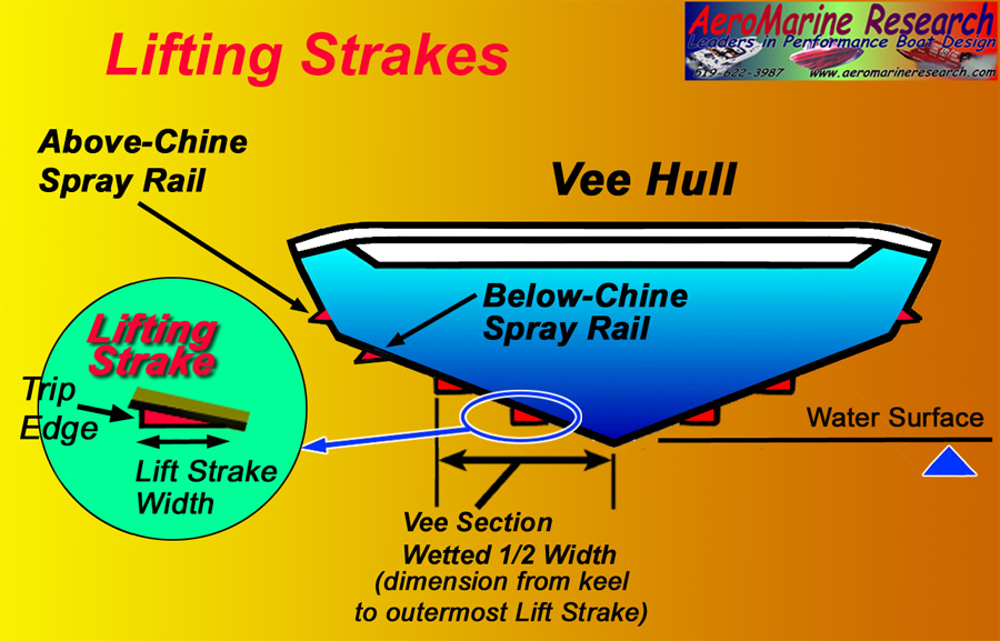
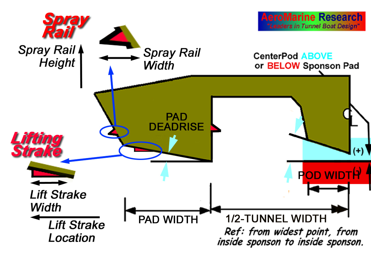
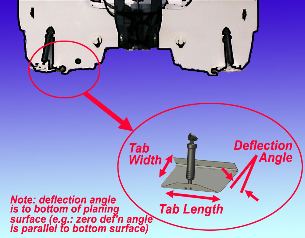
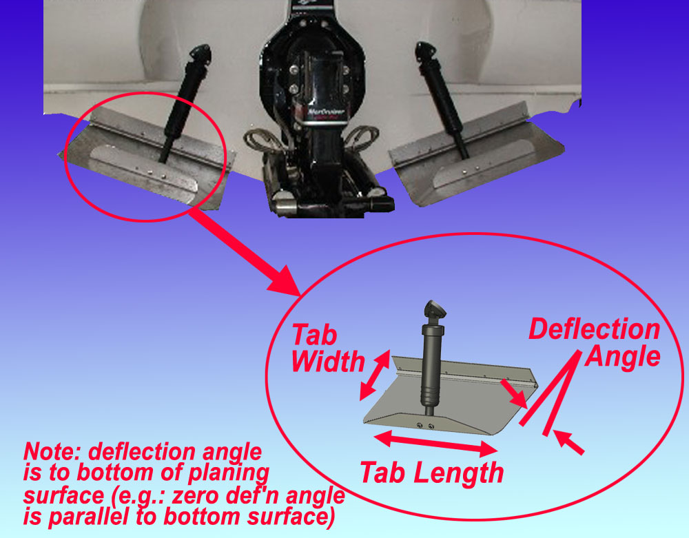
AR® has developed analysis techniques that calculate hydrodynamic lift and drag contributions of Lifting Strakes, Spray Rails and Trim Tabs. These performance aspects are different on tunnel hulls and vee hulls, and so are, of course, handled appropriately for each design, each setup arrangement and different at each operating velocity. It's important to recognize that Spray Rails and Lifting Strakes are different. Spray rails are usually located on the outer chine surface, about half-way between sponson bottom and deck (sheer clamp). Outer spray rails can improve hydrodynamic lift at lower CLW's (lower velocities) and reduce induced spray drag. Lifting Strakes are located on planing surfaces, are designed to have a surface generally flat (zero deadrise) to water surface, and generate increased lift at improved efficiency under some conditions. [Spray Rail Design - Spray deflector should be triangular in shape with it's bottom nearly horizontal to the water surface – or at a slight upward (8°) angle. The "downward" angled spray rails seen on some boats are less than optimum for effectively diverting the spray away from the hull surface. The outer edge of the spray rail should be sharp and not rounded] Lifting Strakes can be specified for tunnel hull or Vee hull configurations. TBDP©/VBDP© accounts for [Lift Strake Design: High-lift strakes are located symmetrically (on both sides of the keel) and parallel to the keel of the hull. They are triangular in shape with their lower surface flat and horizontal (parallel) to the water surface. The corner/edge of the strake should be sharp, not rounded.] TBDP©/VBDP© now accounts for the use of Trim Tabs in your hull setup. Select use of Trim Tabs by selecting the TrimTab checkbox on Input Screen #4. Input dimensions for Tab Width, Tab Length and Tab Deflection (degrees, “+ve” input means deflected Tab DOWN to water; “-ve” input means retracted Tab UP). TBDP©/VBDP© assumes that there are 2 Tabs for all installations (input dimensions are for each (1) Tab. [Note: Caution should be used when defining dimensions and setup of Trim Tabs (and particularly in actual use with your hull on the water). Trim Tabs that are sized or setup so as to provide a significant % of the total lift of the hull can create instability. Tabs should be retracted when hulls are at higher velocities.] |
|