|
|
|
|
|
Advanced Aerodynamics and Hydrodynamics for Powerboats |
| Performance Boat design and setup secrets for Recreational tunnels, Offshore Cats, Racing tunnels, Fishing/Utility hulls, Vee and Vee-Pad Hulls, Bass Boats | |
| Home New About Us Free Articles Technical Articles TBPNews Archives FREE Downloads Research Contact Us | |
|
Testimonials
What Others Say
Join TBPNews
Advertise
Search
Buy Now
|
|
|
|
|
| VBDP© Vee Pad Performance Analysis | ||
| Get complete article by email request: | Share: | |
| BREAKTHROUGH! | |||
 Figure 1- VBDP© graphic output shows the velocity at which your hull configuration experiences instability in Porpoise Regime and susceptibility to porpoising. 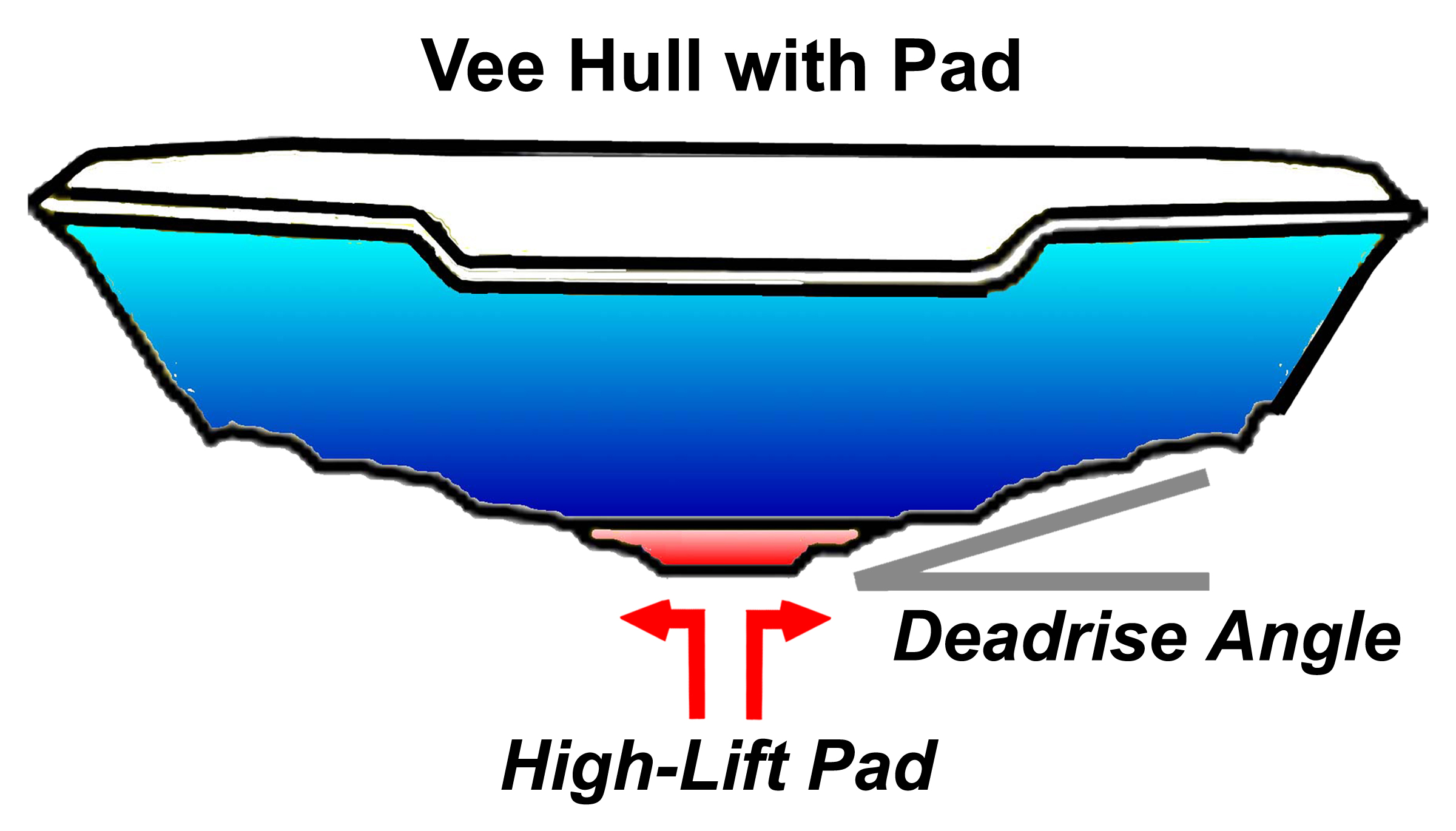 Figure 2- Vee-Pad configuration can be analyzed to optimize center-pad width, length, deadrise, height. 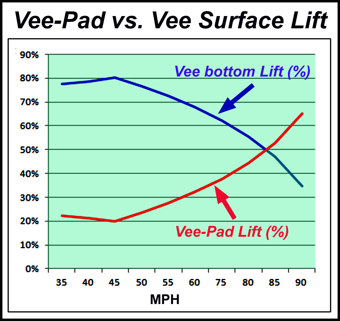 Figure 3- Effective balancing of Vee-Pad Lift can optimize balance of 'Pad Lift' with 'Vee surface Lift', based on hull weight, configuration, power and speed requirements. 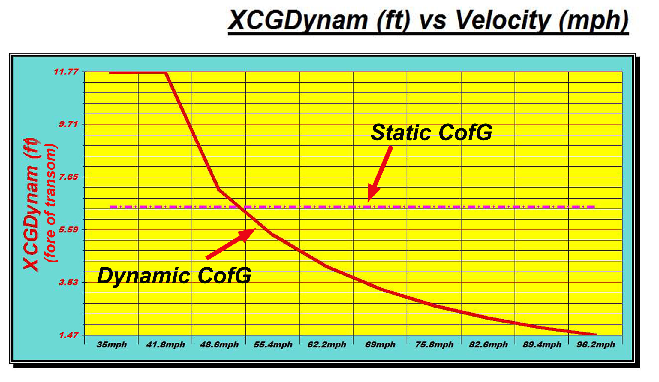 Figure 4- The important 'Dynamic CG' location changes dramatically throughout the operating velocity range of the hull; while the 'Static CG' of boat remains in the same location.  Figure 5-VBDP© software employs unique "Vee-Pad design optimization" technique to provide detailed performance prediction results for easy 'balancing' of vee-pad/vee surface load distribution for any vee hull design/setup arrangement. |
Vee-Pad design optimization is a delicate balance, solved by AR's
unique analysis and VBDP© software. We have developed a unique analysis technique that allows designers to see the delicate balance between lift/drag forces of a vee-pad hull. The method can isolate the lift/drag forces for vee-pad, vee (bottom) surfaces, aerodynamic surfaces and lower-unit appendages. The technique gives designers, builders, owners and operators the ability to optimize vee-pad dimensions and setup to fine-tune the lift gained from the "pad" portion and "vee surface" portions of hull design. The VBDP© software employs the unique "Vee-Pad design optimization" technique and provides detailed performance prediction results and graphic performance output that allows for easy 'balancing' of vee-pad/vee surface load distribution for any vee hull design/setup arrangement.
How it Works The pad is a relatively flat planing surface configured to the aftmost section of a vee shaped hull. The pad (or low deadrise center-section) usually extends sufficiently forward, so that the transition from the vee to the flat running surface is gradual, and usually exhibits some deadrise in the forward section of the extension. The pad has several performance advantages: Balancing Act - the high-performance vee-bottom can be a challenge to drive at high speed. Deeper vies (15°–20°deadrise) must be balanced on a thin keel edge, often exhibiting an unsettling lateral instability, as it “rocks” from side to side. The pad provides a wider platform on which the hull will ride - making it easier to balance at higher speeds. High Lift - The flat pad generates much more efficient Lift than the veg'd bottom shape. Hydrodynamic theory dictates that, in general, a steeper angle of vee (e.g. 20° deadrise)creates less Lift than a shallow angle (e.g. 10° deadrise). The extreme case is the completely flat pad that has zero (0° deadrise) that creates very high Lift for it’s small wetted surface area. The result of this “extra Lift” is reduced hydrodynamic Drag and more speed!
Optimization of Vee-Pad design - Vee-pad design dimensions and configurations have traditionally been established by "trial-and-error" methods or "duplication" of other designs. These methods can be costly, time consuming and can generate disappointing final results since the ultimate design is not necessarily optimized for the subject design hull. The AR© "Vee-Pad design optimization" technique allows us to attain an effective 'balance' of vee-pad/vee surface load distribution for any vee hull design/setup arrangement. This 'balance' of 'Pad Lift' with 'Vee surface Lift', should be optimized for each unique hull design, setup and operating conditions. Optimization of vee-pad dimensions must be based on unique boat weight, hull configuration, power and speed requirements. Vee-pad characteristics can then be established, including: -pad width -pad length -pad deadrise -pad height All of these characteristics affect the efficiency of the "high lifting pad" and the portion (%) of Total hull Lift that the pad can provide. Dynamic Stability - The 'Static CG' of a hull is the location of balance of the hull and payload deadweights while boat is at rest. But this is a small part of the important balance of a performance hull. (You can't balance your boat on the trailer!) The combined center of ALL the LIFT forces and all the DRAG forces (sponsons, center-pod, vee surfaces, center-pad, aerodynamic surfaces, lower unit, etc.) while a boat is under way, is called the 'Dynamic Center of Forces' or 'Dynamic CG'. The 'Dynamic CG' location changes throughout the operating velocity range and is the most important design measure to consider when 'balancing' a performance boat. Especially at key velocities, dynamic stability is maximized when the Static CG is close to the Dynamic Stability location. The unique balance of vee-pad forces and vee surface forces in a vee-pad hull make the DYNAMIC balance of the hull important in the design process. [see also AR's 'Advanced Dynamic Stability Analysis research brief'] Results - The "Vee-Pad design optimization" analysis approach can complete an effective 'balance' of vee-pad/vee surface load distribution that will maximize performance and improve dynamic stability. |
||
|
Research results now included in performance
analysis by TBDP©/VBDP© [more about AR's research more about AR's publications and technical articles/papers] |
|||
|
© Copyright 2018 by
Jim Russell and AeroMarine Research® - all rights reserved. Material from this website may not be copied or used or redistributed, in whole or in part, without the specific written consent of Jim Russell or AeroMarine Research. |
|||