|
|
|
|
|
Advanced Aerodynamics and Hydrodynamics for Powerboats |
| Performance Boat design and setup secrets for Recreational tunnels, Offshore Cats, Racing tunnels, Fishing/Utility hulls, Vee and Vee-Pad Hulls, Bass Boats | |
| Home New About Us Free Articles Technical Articles TBPNews Archives FREE Downloads Research Contact Us | |
|
Testimonials
What Others Say
Join TBPNews
Advertise
Search
Buy Now
|
|
|
|
|
| AR© develops Drive Unit Drag Analysis with TBDP©/VBDP© | ||
| Get complete article by email request: | Share: | |
|
ADVANTAGE |
||
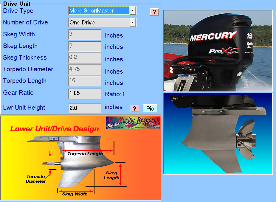
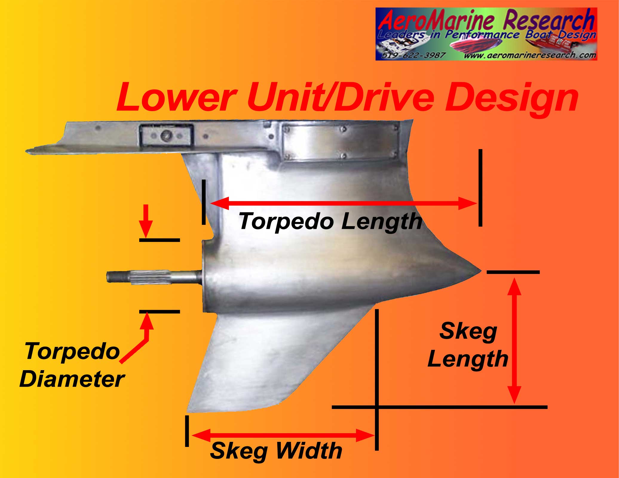 Figure 1 - Lower Unit Drag design & dimensional inputs
|
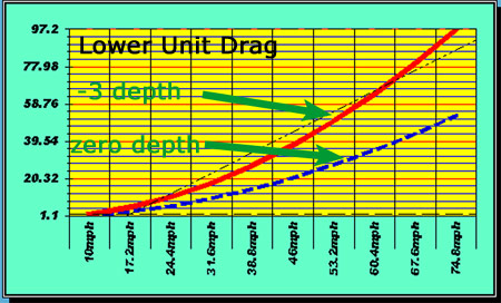
TBDP©/VBDP© Drive Unit Drag Analysis calculate
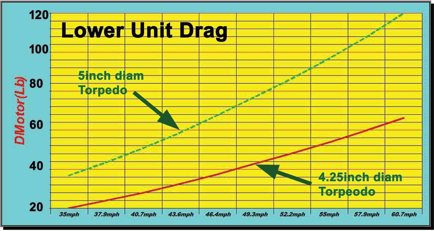
drag and coefficients for ANY drive design configuration throughout the entire hull operating velocity range AR® has developed complex algorithms that calculate hydrodynamic drag of the outboard lower unit or I/O outdrive design & configuration. This performance is different for each design, each setup arrangement and drag contributors are different at each operating velocity.
The Appendage drag of motor or outdrive lower unit is difficult to calculate in a simple manner. There are many different designs of outboard lower units in use today; every boat will have the lower unit set up with respect to the hull differently; and there are several contributing drag components (see below) that determine the overall drag of the lower unit.
The fluid flow field around the lower unit components exists in all of water, water vapour (cavitation), air and exhaust gases. All of these constituents and fluid phases are exposed to interaction with the lower unit.
TBDP©/VBDP© now calculates hydrodynamic drag of ANY lower unit design; includes standard design specs for OEM drives, including NEW massive Yamaha and Mercury HD 350hp drives, Merc TorqueMaster, SportMaster, and FleetMaster drives; Merc M8 and Drysump outdrives, Merc Verado 350Sci HD, Merc SSM4, Merc SSM6, Nissan & Tohatsu SportC, Tohatsu 50HP D-Stock foot, Suzuki DF and Evinrude ETec HO and G2 gearcases, Alpha, Bravo, Volvo IO drives, Imco SCX, Ilmor Indy drives, even Arneson surface drives and RC outdrives, direct (inboard) drives. How It Works: Hydrodynamic drag is calculated for each of key drag contributors based on the conditions throughout the entire operating velocity range. Motor height and trim angle affects how much of the drive unit is immersed in flow, generating drag. The contributors to overall drive unit drag include components of friction drag, pressure drag, spray drag and induced drag from:
Some of the design inputs include:
TBDP©/VBDP© software generates accurate performance prediction: AR software generates accurate performance results throughout the full operating velocity range, showing the total hydrodynamic drags at Drive/Lower Unit AND the impact on overall performance. Compare quickly what the performance differences are through the velocity range for:
Determine quickly effects of drive unit design/setup on:
Your results are unique to your hull design, engine power and boat setup - so just input the info to TBDP©/VBDP© and complete the 1-2-3 performance analysis to easily see the results differences with your before/after case:
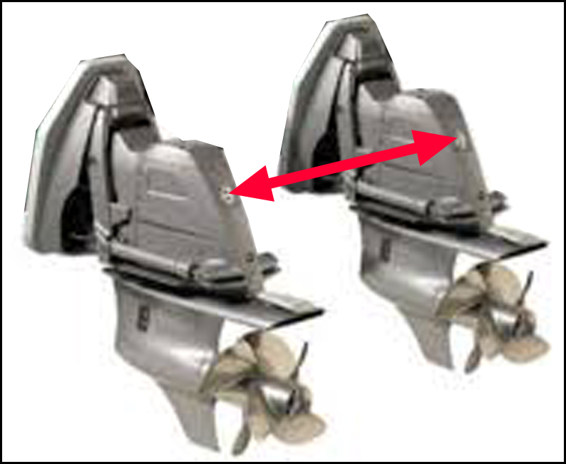
Research has also shown that interference drag occurs when lower units of multi-engine (outboard or sterndrive) installations are located in close proximity to each other. As lower units are closer together, interference drag can become significant. AR® has developed analysis techniques for calculating 'multi-engine interference drag' and TBDP©/VBDP© accounts for this drag based on lower unit configuration and multi-unit spacing. |
|
|
||
|
The Drive Unit hydrodynamic drag results are
presented in standard
TBDP©
and
VBDP©
output and in graphic analysis format.
TBDP©/VBDP© makes it easy to see the performance and stability improvements that are achieved by design modifications and/or setup changes. |
||
|
[more about AR's research more about AR's publications and technical articles/papers] |
||
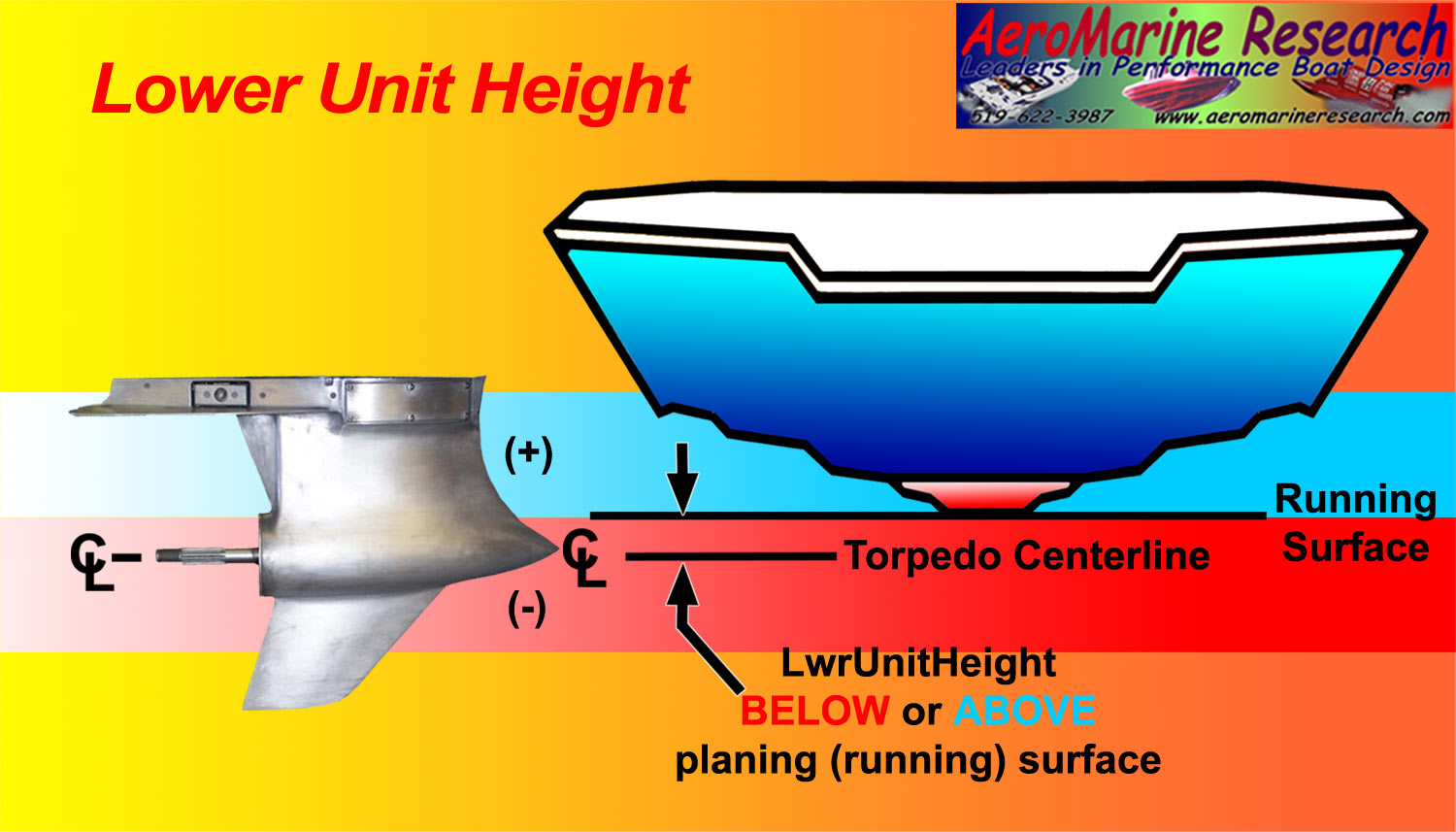
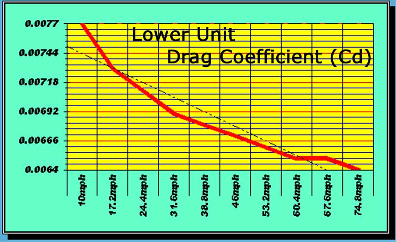
 The TBDP©/VBDP© analyzes the specified design of the skeg,
the leg, the torpedo and the propeller, and calculates the overall hydrodynamic drag and drag coefficient based on configuration and relative velocities. Height of the lower unit relative to the water surface and hull planing surfaces is also included in the analysis.
The TBDP©/VBDP© analyzes the specified design of the skeg,
the leg, the torpedo and the propeller, and calculates the overall hydrodynamic drag and drag coefficient based on configuration and relative velocities. Height of the lower unit relative to the water surface and hull planing surfaces is also included in the analysis.